- Lightning and Overvoltage Protection
- +90 212 210 27 28
- info@yilkomer.com
Seperation Distance And Isolated Lightning Down Conductor
September 25, 2015Lightning Protection Zones and Classes Of Surge Protectıon Devices and Installation
September 26, 2015Surge Protectıon Of Inverters

Inverter system should be protected by surge arrester system
In ancient times, people believed lightning is a consequence of god’s anger; later in time, the common belief was that lightning is a result of cloud collisions. Today we have much better understanding of the lightning phenomenon, explained as a great electrostatic discharge between electrically charged regions within clouds, or between a cloud and the Earth. The charged regions equalize their potential with a fast lightning flash, commonly referred to as “Lightning Strike”. Lightning occurs approximately 40-50 times a second worldwide, resulting in nearly 1.4 billion flashes per year.
The electrical current within a typical lightning strike, behaves as a sharp edge pulse which rises to its peak value very quickly – in 1–10 microseconds – and decays over 50–200 microseconds. The transient nature of the current within a lightning flash results in electrical effects, from which ground and roof-based structures need protection.
Electrical components are particularly susceptible to lightning effects and their design needs to account for this. This document describes the various effects and the corresponding protection in the devices.
Read More: Surge Protection for Photovoltaic System
Lightning Strikes and Electromagnetic Pulses
The rapidly changing currents create electromagnetic pulses (EMPs) that radiate and create current and voltage “surge” when passing over conductive elements like electrical wires, communication lines, or metallic pipes. These surges may result in the destruction of delicate electronics and especially semiconductors. Devices known as surge protectors (SPD) or transient voltage surge suppressors (TVSS) connected to these conductors can route these transient currents to the ground, protecting the equipment from damage.
Direct Lightning Strike
Direct lightning strike energy is enormous and a surge protector alone cannot protect the stricken instruments. It is necessary to use external lightning protection to attract the lightning and redirect it to the ground, and use surge protectors only to absorb residual energy. External protection includes lightning rods, grounding wires, catching devices and conductors, as well as the accompanying ground system.
Another effect of the direct lightning strike is increased ground potential – When the lightning strikes a building or a lightning rod, high current flows to the ground and the ground potential rises. This creates a potential difference that leads to surge behavior, and is protected from in a similar way to induced lightning surge protection.
Electrostatic Induction
When thunderclouds located above a power cable or a communication cable, contain negative charges at their lower sections, high-level positive charges electrostatically induced within the cable, and high voltage is developed. When the positive charge which is trapped in the cable is released (during discharge), it results in a voltage surge in both directions of the cable. Electromagnetic Induction (Indirect Lightning)
According to Ampere and Faraday’s laws of electromagnetics, a discharge between the clouds and the ground, occurring near a power or communication line, generates a magnetic field pulse wave. When the magnetic waves propagated within the field reach the cable, they induce a voltage surge.
Surge Protection of Inverters
The inverters and power optimizers conform to the IEC62109 safety standard. According to this standard, equipment permanently connected to AC must withstand Overvoltage Category III (marked OVC III), while DC connection must withstand OVC II. Impulse-withstand voltage ratings for the mains circuit are assigned based on the above OVC and on the mains system voltage, as in section 7.3.7.1.4 of IEC62109 and is >4kV. The inverter is manufactured with internal overvoltage protection on the AC and DC (PV) sides. If the PV system is installed on a building with an existing lightning protection system, the PV system must also be properly included in the lightning protection system. The inverters are classified as having Type III (class D) protection (limited protection). Varistors in the inverter are connected between phase and neutral cables, between neutral and PE cables, and between PV plus and PV minus terminals. The power optimizers have the same protection level as regular protection diodes that exist in every PV module. This means that the power optimizers can withstand the same surge events and voltages as the PV module.
What is a Surge Protection Device?
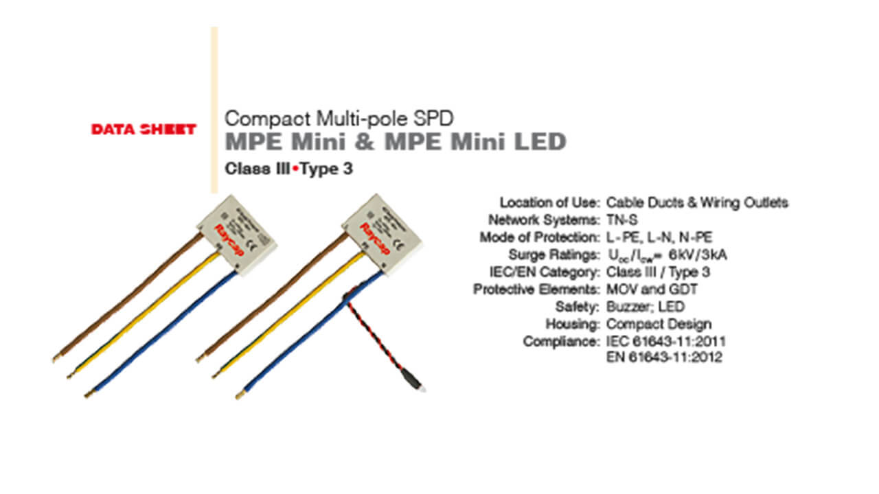
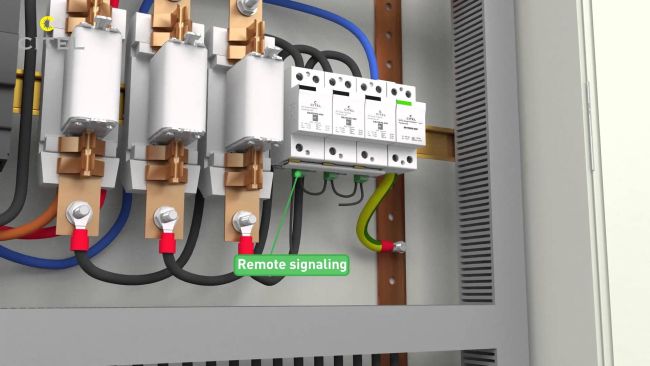
In order to avoid high voltage damage to a PV system, all of the lines and conductive surfaces should be grounded directly or through a Surge Protection Device (SPD), which creates an equipotential bonding between the connected conductors. Live cables such as mains connection or telephone lines are indirectly connected to the ground system using the SPD. The Surge Protection Devices are usually a combination of Metal Oxide Varistors (MOV) and/or Gas Discharge Tubes (GDT) acting like a diode (or Zener diode) shunting the current created by the high voltage away from protected sensitive areas when triggered. Both MOVs and GDTs have a limited lifetime, and can handle a finite number of transients. The SPDs are divided into three classes ranging from Class I – Highest protection, to Class III – Lowest protection against far lightning inducted surges.
Adding an External SPD to Your PV System
When using string protectors such as fuses, DC breakers or string diodes together with SPDs, the SPD must be installed between the fuses and the inverter, otherwise the PV strings would be unprotected if the fuse is triggered
For inverters with an integrated fuse box, internal fuses should be bypassed in order to connect an SPD, and external string fuses should be connected.
AC Side – Inverters can be connected to the same SPD if they are sharing the same grid connection.
Protecting the Communication Lines
Power lines are not the only conductive cables that can induce voltage surges into the inverter electronics. The communication lines (RS485 and Ethernet) should also be protected using external designated surge protection in cases where there is a risk of induced surges. YILKOMER recommends using external surge protection devices on the communication lines in sites with the following two properties:
- The distance between devices is more than 10 m/33 ft
- There is a risk of induced surges
RS485 surge protection – surge discharge ratings of In: 10kA 8/20μs and Imax: 20kA 8/20μs
RS485 protection should be according to the following wiring specifications:
Cable type: Min. 3-wire shielded twisted pair (a 4-wire cable may be used)
Wire cross-section area: 0.2- 1 mm²/ 24-18 AWG (a CAT5 cable may be used)
Maximum nodes: 32
Maximum distance between first and last devices: 1 km /3300 ft.
Ethernet surge protection – surge discharge ratings of In: 10kA 8/20μs and Imax: 20kA 8/20μs
Ethernet protection should be according to the following cable specifications:
Cable type – CAT5/CAT6: Maximum distance between the inverter and the router – 100 m/ 330


